1998 October 29 (Thursday)
I created the stand noted previously. It needed some spacers or cross braces to work correctly. As initially built is is kind of wobbly.
Horn
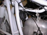
horn
Before removing the engine I removed the horn. This on one of the things known to be broken. I’ll take it apart and see if there is anything I can do to fix it later. Ed Korn says pulling the horn apart, cleaning the contact points and adjusting the contact arm screw will often get them working, again.
Front engine cover
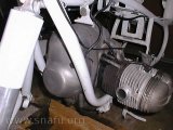
Front cover on bike
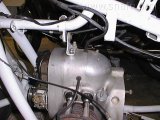
Front cover removed
Once the horn was removed the front timing cover came off. The cover attaching screws have 10 mm heads and for some reason I thought they were supposed to be 14 mm. It’s turned out to be one of those items that the factory changed over the years. Eventually I found some after marker stainless screws that happened to be 14 mm.
Breather cover
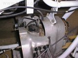
breather filter
After the front timing cover the top breather cover is removed. Under the breather cover is a filter insert, rubber gasket, and clamping spring. I removed them. I wondered if the filter insert could be cleaned… Yep.
Note: BMW stopped putting a channel between the air chamber and the front of the engine in later years.
Generator wiring
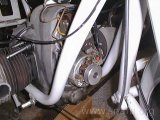
Generator wiring
Five wires needed to be removed, two brown, two red, and a blue. I noted which goes where in my notebook and then disconnected them and pulled them out of the engine from the breather opening. Also noted was wire routing inside the front cover.
Vibration damper
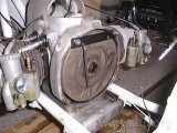
locking the flywheel
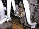
vibration damper parts
The first pictures shows the tool I used to hold the flywheel so I could remove the shaft from the front of the generator. The thing that looks like a pulley used to hold the vibration dampener. The damper was often removed.
On this bike the damping mass, slip washers, and rubber spring were missing but the bracket to hold the mass was still on the nose of the crank.
The inside of the front cover was coated with a layer of black rubber, right around the circumference of the “bulge”. I’m guessing it is the remains of a vibration damper “spring”. Most of the stain was removed when cleaning the cover.
Generator
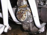
Generator
The generator and attached voltage regulator came off after removing the two allan head bolts that hold the assembly to the case. The armature was removed by inserting a special bolt and tightening it until the armature pops off. Eventually.
Armature removal tool
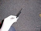
Bent armature puller
Sometimes the armature sticks and it needs lots of pressure before it pops off. The removal tool at the left used to be straight. It was actually worse than can be seen in the picture as it is bent in three dimensions; you can’t see the bends toward the camera!
<plug> This tool and the tool used to hold the flywheel come from CYCLE WORKS INC. Ed Korn, the proprietor, wouldn’t let me pay for the replacement. He’s also updated the instructions that come with the tool for those that run into a similar problem.</plug>
Top engine mount
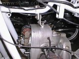
Top engine mount
The top engine mount was disconnected from the engine and from the tube clamp. Checking with the parts book shows that mine was installed quite differently from the exploded parts list. Both ways were written in my notebook.
Engine removal
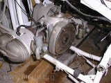
carburetors
The carburetor slides needed to be removed. The slides and covers are gently routed on top of the frame to get them out of the way.
Some wood blocks were inserted under the engine to support it while I drove the mounting bolts out with a drift. The front bolt did not look standard. I believe it is too long and there are different threads on the two ends. There were spacers on the left side both front and rear. However, the parts book notes some bushings that I don’t see.
The engine is HEAVY! I got it out of the frame and onto the mini-stand I made. That is when I found out that the stand needs cross braces or something similar.
Empty frame
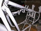
Engine removed
The tube clamp for the upper engine mount was removed. The frame was looking pretty bare without engine and transmission.