1999 June 21 (Monday) [continued]
Drive-shaft

Drive-shaft and swing-arm

Installing drive-shaft
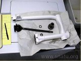
The drive shaft needs to be installed into the painted swing-arm before the swing-arm can go back on the frame. I cleaned the cone at the end of the shaft and the matching surface on the drive hub with an alcohol swab before installing the hub and torquing it down.
My torque wrench only goes to 75 ft-lbs. Therefore I know it’s torqued at least that much. I’ve since purchased a third (and fourth!) torque wrench to handle larger (and smaller) torque values.
Rear swing-arm bearings

Rear swing-arm bearings
After the drive shaft I installed races, bearings, sleeves, seals, etc. I loaded the roller bearings with as much grease as I could. of grease.
Rear swing-arm installed

Rear swing-arm installed
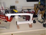
I installed the swing-arm on the frame and centered it using drill bit shanks as a gauge. I following the instructions in the book in setting the bearing pre-load, tightening one pivot 1/8 turn beyond the point there was no side-to-side play. I then attached the swing-arm to the left shock assembly. It’s beginning to look like a bike, again.
Rear brake linkage incorretly assembled

Rear brake linkage incorrectly assembled
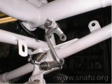
This picture is a close up of the rear brake linkage. I used a new bushing in the bell crank, zinc coated the rods and crank, and used stainless fasteners. It looked good. Too bad it was done the wrong way. There are two errors with this picture. First error: The castle nut on the bell crank should be facing out not in. As it is in the picture the nut and bolt will rub against the fender, gouging it in an arc when the swing-arm pivots up and down.
I discovered this the hard way. Second error: The bell crank is turned 180 degrees. The longer arm should be attached to the brake lever through the short rod. I didn’t realize I had it wrong until Oct 2008! The rear brakes work much better when everything is correctly connected.
The dabs of black is left over grease. Every place metal touched metal was greased.
Front shock assembly

Front shocks
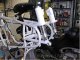
These are the front shock assemblies. They were not finished in this picture because I didn’t have the tool necessary to keep the springs compressed while I tighten the upper eye to the shock strut. I did that later at Joe’s. I also now have the tool to do it myself. New silent blocks were pressed into both upper and lower eyes.