Well, it had to happen. While removing the plastic that covers the handle bars to see where to route power for GPS and/or radar detector the tip of the torx driver fell into the bowels of the beast, not to be retrieved with magnetic wand. With a 3 mm allen wrench and a T-25 torx driver I started removing things until I reached my goal. Of course too much was removed. Next time I’ll know. Oh yeah: the plastic was held on with a 3 mm allen screw; it was just a coincidence that the T-15 torx driver fit.
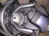
This was the goal. A T-15 torx tip for a drill that I was trying to use in a 1/4 inch nut driver. Now I own a set of real torx drivers.
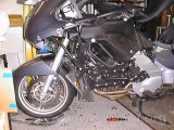
Those black spots on the rug are NOT bugs, but the screws that held the left side on. No, I did not have to remove the lowers to remove the upper side. This made the right side go faster. Yes, I had to remove the right side to remove the radio console to get to the lost tool.
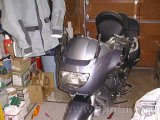
From the front. No, the windshield did not need to be removed.
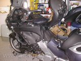
Just another angle with things apart. You can see the windshield leaning against the washing machine in the background. The funny plastic piece with the dimples is the gas tank.
Later…
The above was good practice. The second time I took the plastic off was to get power to the GPS and Radar detector. Here are the steps. But first…
- Pay attenting to what size screw goes where – two lengths of T-25 screws are used in addition to the allen head screws.
- Don’t force anything. If you have to force it you’ve probably missed a screw someplace.
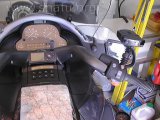
The GPS is mounted using velcro. I’ve a Saeng/TA mount for the Radar detector. Now it’s time to remove the plastic to get to the needed power. I’m going to tap into the lead that goes to the lower accessory socket.
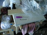
These are the tools needed. Almost. I forgot that you also need a philips screwdriver to take off the turn indicator lens.
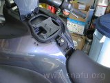
The top cover is held on with two screws. Don’t force the cover off after removing the screws – there are two plastic hooks that help hold the cover down. Slide the cover toward the seat to release these hooks.
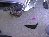
The side bumpers are held on with two screws. They come off quite fast. You can see the crash tube under the bumpers.
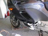
This picture shows the plastic/chrome trim removed. This bit of trim needs to be gently squeezed where it attaches to the upper and lower plastic toward the front of the bike. It is held on by two allen head screws at the bottom of the trim and one torx screw where it wraps around the plastic by the riders knee/shins.
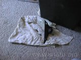
The lower wind deflectors are removed next. Each is held on with three screws. Now is also a good time to remove the mirrors. A rap to the back of the mirrow with the heel of your hand will pop them loose.
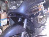
Next the turn indicator covers are removed. This is where a phillips screwdriver is needed. I removed the bulb sockets from the covers and put the covers someplace I wouldn’t step on them.
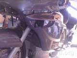
At this point you can see all of the screws holding on the front side covers. Remove the screws and then pull the rear of the front side cover out from the front of the rear side cover. Confused? The two pieces of the side covers are joined under with a pin-and-grommet. They must be separated. Once that is done pull from the bottom of the cover a few inches, then lift the cover up. That removes the tabs at the top of the side cover from the slots in the top piece.
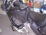
This shows the side covers removed.
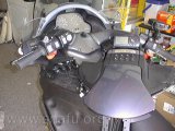
The screws holding the radio/top cover are removed and the unit is moved out of the way enough to route my power cables. I’d have to remove a half-dozen or so electrical connections if I want to completely remove this cover. This way I can still listen to a CD while I’m working.
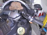
The plastic covering the handlebars is held on with two 3 mm allen head screws. This is where I’m routing the power cable to the radar detector.
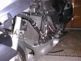
The white cable ties on the frame member is the power distribution box that came with the radar detector. I used it to power the GPS, too. It is wired to the accessory socket hot lead and chassis ground. The bundle of wires is the excess from the GPS and radar detector power leads. There are also cable tied to the frame and out of the way. I made sure that they didn’t interfere with the fit of the side covers.
Note: Once you’ve gone this far it becomes obvious how to remove lowers and front piece.
More plastic removal: headlight switch (by Nils Powell)
Nils bini@tassie.net.au used the above as the starting point for installing a headlight switch. These are his comments…
Did the h’light sw today. A couple of additions to your notes.
The wiring connector plugs and relays are under a cover held by 4 screws which is covered by the fan duct and tank on the right hand side. This can only be reached by removing both fairing sides as you describe. The connector plugs are for H’bar switches left&right, instrument cluster, ignition switch, light sw, hall sensor, kill sw, stop light relay.
Then
- Loosen radio panel so it is free to move & disconnect the 3 elec plugs at the fwd Left hand end.
- Remove 5 allen bolts holding the metal frame which is the seat support, but do not remove seat. this frame should now come free.
- Remove 2 allen bolts holding the petrol tank and carefully pull the tank back together with the radio panel, seat support frame and seat. About 3 inches gives access and only one elec connector at the rt rear tank top has to be disconnected.
- Remove the Right hand fan ducting - 2 screws.
The connector block can then be opened.
The job took about 3 hrs when we converted the hard wired headlights to ones operated by a switch on the right handlebar which had to be changed.