1998 November 3 (Tuesday)
Circuit diagram
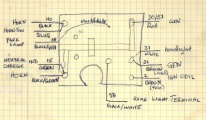
circuit board wiring
I had the headlight apart earlier this spring to fix a problem with the circuit board. I am not going to remove the circuit board this time as the metal tabs that hold it in place can only be bent so many times: there is no need to stress them this time as the board and switch assembly were repaired not long ago. The circuit board will have to be well masked when the bucket is painted.
Headlight
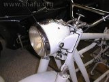
headlight bucket

headlight removal
I removed the retaining screw at the bottom of the chrome ring around the headlight lens to release the headlight from the bucket. Then I removed the wires going to the headlight. After polishing the ring I stored the headlight and lens assembly with other parts that have come off the bike.
Bucket wiring

inside the bucket
I removed all of the wires attached to screw terminals on the circuit board. There are still wires going to the neutral/generator indicators behind the speedometer. I have a schematic drawing of the proper wiring in my notebook from this spring (see above).
Speedometer Cable

speedometer cable routing
I removed the speedometer cable from the speedometer and pulled it through the headlight bucket after popping out the split grommet. The cable and the grommet are stored together in a zip-lock bag. This cable only has a few thousand miles on it and is in excellent condition. The nut that holds the speedometer bracket is removed and the speedometer is lifted out of the bucket.
The O-ring/gasket will need to be replaced. I’ll be sending the speedometer out for repair: the trip odometer can not be reset and the digits on the main odometer can not be read.
Indicator lights
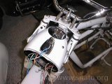
Speedometer removed

Indicator lights
Once the speedometer is gone there is easy access to the neutral/generator indicator lights. The light base is pulled from its housing and the wires are removed. The horn/high beam switch is then pulled from the headlight bucket and put away.
Wiring harness
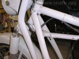
Wiring harness 1

Wiring harness 2
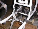
Wiring harness 3
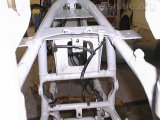
Wiring harness 4
The above series of photos shows how the wiring harness was positioned. I wasn’t sure if it was correct, especially where it went through the front forks. It looked like the way it was it could get pinched when pushing the handlebars to the left.
Wiring harness removed

Wiring harness off bike
This image is the wiring harness removed from the bike. An inspection showed one place where the outer covering was worn through. The insulation of the individual wires was still good, however. I covered the worn area with black electrical tape for now. Will probably use some heat-shrink tubing as a permanent fix, later.
I removed the brake switch, but left the 3 terminal connection block attached to the harness. The connection block is where the tail light wiring attaches to the main harness. Once all the wiring is removed the headlight bucket comes off.
Headlight bucket ears
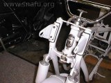
Headlight bucket removed
I removed the headlight mounting ears. The rubber parts are OK and can probably be re-used.
The slide-lock cover is held on with bent tabs. I carefully unbent the tabs and removed the cover and slide from the headlight bucket. I used a very gentle bend when I installed the housing a few months back so it came off without losing any tabs this time.
The neutral/generator lens did not came off easily. There was some minor damage to the lens mounting tabs. It looks like the mounting tabs were melted in place. I think I’ll have to replace this lens. The breakage can’t be seen, but I don’t think there’s enough material left to hold the lens into the bucket.