1999 May 19 (Wednesday)
Today (and part of yesterday) were used to prepare pieces that are going to go back on the bike. I took the wiring harness and, using paint thinner and lots of elbow grease, got most of the over-spray off. The over-spray was from the previous owner’s paint job. I also added heat shrink tubing and/or electrical tape where needed.
Wiring harness prep
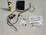
Wiring harness, damper, and axles
The wiring harness and some other parts almost ready to go are pictured. I first painted the damper pressure and friction plates yesterday. Today they got a second coat—that’s the black blob at the top of the picture. The zinc plated steering damper parts can be seen in the foreground. Chrome plated axles are at the right.
Plated axles
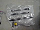
re-chromed axles
This is a closer view of the axles. The bearing surfaces were protected with electrical tape so they would not be re-plated, changing their size. It took a lot of work to get the tape off. (I traded my axles plus cash for these axles—they’d been sitting with the tape on them for quite a while.)
I draped the wiring harness over the frame using pictures taken before the wiring was removed as a guide to placement. Oh, oh…. I was a bad boy and did NOT put the rear brake switch in a baggie and store it with the rest of the parts and now I can’t find it. Looks like some garage clean-up will be necessary before I can install the wiring harness.
1999 May 20 (Thursday)
I finally found the rear brake switch after some searching. I discovered it stored with the speedometer bracket and generator/neutral indicator. Seems like I took those parts off at the same time so stored them together. In order to make sure things were positioned properly I decided to mount the brake lever to the frame, first.
Rear brake linkage components
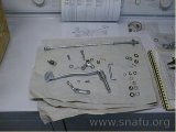
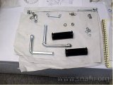
components
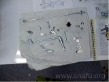
components
These are the brake linkage components, plus the stainless steel hardware that will replace some of the original plated parts. I’m only installing the parts that mount directly to the frame. The brake switch is the black blob in the second photo. A new bushing has already been driven into the bell crank.
Foot-peg rubber
New rubber for pegs
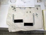
Rubber on pegs
I wanted to make sure the lever was positioned correctly, so needed to mount the foot-pegs, at least temporarily. The pegs are being left in their zinc plated condition. New rubber was soaked in hot water, then slipped over the pegs. It only needed a couple of whacks with a rubber mallet to seat the rubber the last 1/2 inch.
Wrong foot-peg

Wrong foot-peg (top view)
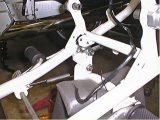
Wrong foot-peg
What’s wrong with these pictures? I must have stared at this for many minutes before I realized I’d swapped the right and left foot-pegs. The brake lever didn’t move freely when first positioned, probably a result of the extra diameter due to zinc plating and a touch of powder inside the mounting hole. A knife and file took care of the powder; some 600 grit paper made the lever nice and smooth.
Foot-brake lever
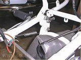
Foot-brake lever
The foot-brake lever was re-mounted with lots of grease. I used the proper foot-peg this time. The brake switch was mounted and the actuating arm positioned and torqued down. The return spring was installed last. Looks good.